Installing OpenOCD
From spiderboard.org
Contents
Installing OpenOCD (Linux)
- OpenOCD Version >= 0.10 with the libftdi driver is required.
- If your package distributor provides this version, use your package manager to install OpenOCD:
- For Debian based distributions the terminal command is:
- $ sudo apt install openocd
- If the package version does not work, it is possible to compile OpenOCD from source (github).
Installing OpenOCD (Windows)
- OpenOCD Version >= 0.10 with the libftdi driver is required.
- Prebuild binaries of OpenOCD can be downloaded from here
- Install the libusbK driver for the JTAG interface
- Download and start Zadig
- Select MX10/Spider JTAG (Interface 0) and libusbK driver and click Install Driver.

Shell Script For Easier Use (Linux)
A shell script can be used that starts OpenOCD, runs the svf file and shuts down afterwards, allowing conveniently programming the FPGA using a single terminal command.
- Create the file mx10spider under .local/bin in your home directory and insert the content below.
- If not already done, add .local/bin to the path variable.
- Open .profile in your home directory with a text editor and add the line:
- PATH=".local/bin:$PATH"
- Logout and login again or run the following command to reload the path variable:
- $ source ~/.profile
- Open .profile in your home directory with a text editor and add the line:
- Open a terminal and add the executable flag.
- $ chmod +x .local/bin/mx10spider
- You are now ready to program the fpga using the command:
- $ mx10spider <path/to/file.svf>
- If your project is for example located under /opt/quartus_projects/Example, use one of the following commands:
- $ mx10spider /opt/quartus_projects/Example/output_files/Example.svf
- $ mx10spider /opt/quartus_projects/Example/output_files/Example_pof.svf
- for programming the .sof or .pof file respectively.
mx10spider:
#!/bin/sh

me=$(basename $0)

if [ -f "$1" ]; then

    openocd -c "interface usb_blaster" -c "usb_blaster_lowlevel_driver ftdi" -c "usb_blaster_vid_pid 0x04d8 0xefd0" -c "jtag newtap max10 tap -irlen 10 -expected-id 0x31810dd -expected-id 0x318a0dd \
	-expected-id 0x31820dd -expected-id 0x31830dd -expected-id 0x31840dd \
	-expected-id 0x318d0dd -expected-id 0x31850dd -expected-id 0x31010dd \
	-expected-id 0x310a0dd -expected-id 0x31020dd -expected-id 0x31030dd \
	-expected-id 0x31040dd -expected-id 0x310d0dd -expected-id 0x31050dd" -c "init" -c "svf $1 progress" -c "shutdown"

elif [ "$1" = "" ]; then

	echo -e "\tError: No file specified.\n\tUsage: $me <file.svf>"

elif [ "$1" = "-h" ] || [ "$1" = "--help" ]; then

	echo -e "\tUtility script to start openocd and run an svf file.\n\tUsage: $me <file.svf>"

else

    echo -e "\tFile not found: $1\n\tUsage: $me <file.svf>"

fi
CMD Script For Easier Use (Windows)
A CMD script can be used that starts OpenOCD, runs the svf file and shuts down afterwards, allowing conveniently programming the FPGA using a single console command.
- Create the directory OpenOCD\cmd and the file mx10spider.cmd in this directory.
- Insert the content in this file from below.
- Add the folder to the path variable.
- Now you can open a console and use the command:
- mx10spider <path\to\file.svf>

For this script OpenOCD was installed under C:\OpenOCD\bin\openocd.exe, adjust this path as necessary.
mx10spider.cmd
"C:\OpenOCD\bin\openocd.exe" -c "interface usb_blaster" -c "usb_blaster_lowlevel_driver ftdi" -c "usb_blaster_vid_pid 0x04d8 0xefd0" -c "jtag newtap max10 tap -irlen 10 -expected-id 0x31810dd -expected-id 0x318a0dd -expected-id 0x31820dd -expected-id 0x31830dd -expected-id 0x31840dd -expected-id 0x318d0dd -expected-id 0x31850dd -expected-id 0x31010dd -expected-id 0x310a0dd -expected-id 0x31020dd -expected-id 0x31030dd -expected-id 0x31040dd -expected-id 0x310d0dd -expected-id 0x31050dd" -c "init" -c "svf %1 progress" -c "shutdown"
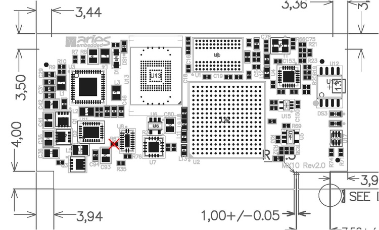
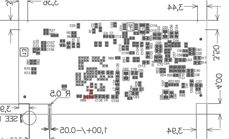
MX10 Hardware Issue
Due to a hardware issue on the MX10, in order to get PIC JTAG programming through OpenOCD to work, one has to desolder four resistors on the module.